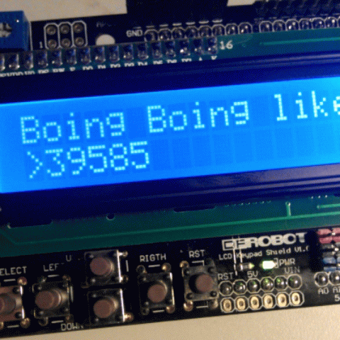

The experiment 8 is going to inmerse you in the world of open hardware, specifically the Arduino technology. This is a easy tutorial that will allow you to build your own "Facebook Like Box". This is a simple gadget, nothing more than a small device that will keep you updated on the number of likes on your facebook page. This are the instructions for mounting a basic model that can be used as a desktop gadget or as a inshop gadget (in a visible place for your customers to know that you have a presence on Facebook). Or what you go through your head.
The project is designed to not have to practice any soldering and simplify the assembly, but need to buy 3 components and 2 cables to do it:
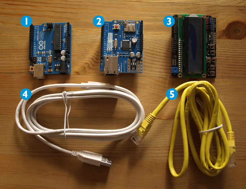
In the Arduino site there is a large list of possible stores in which to buy this material.
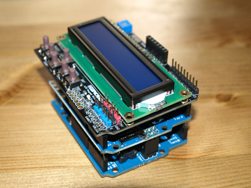
This step is easy, consisting on mount the board 2 on the board 1 through the available pins of board 2. The assembly should look like the one pictured.
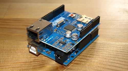
This step is also simple, consists of mounting boars 1+2 with board 3 using the available pins of the board 3. Installation should be as Photo.
In this step, connect the two cables. One of the cables, the gray cable, is for connecting the mounted board with your computer (for energy transfer). You can do it as show in the photo. One end is connected to the board (photo A) and the other one is connected to a free USB port of your computer (photo B).

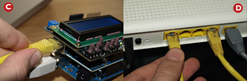
The other cable, the yellow one, is for connecting the mounted board to internet (this time for data transfer). One end must be plugged to the board (photo C) and the other end must be plugged to an access to an internet connection, your router for example (photo D).
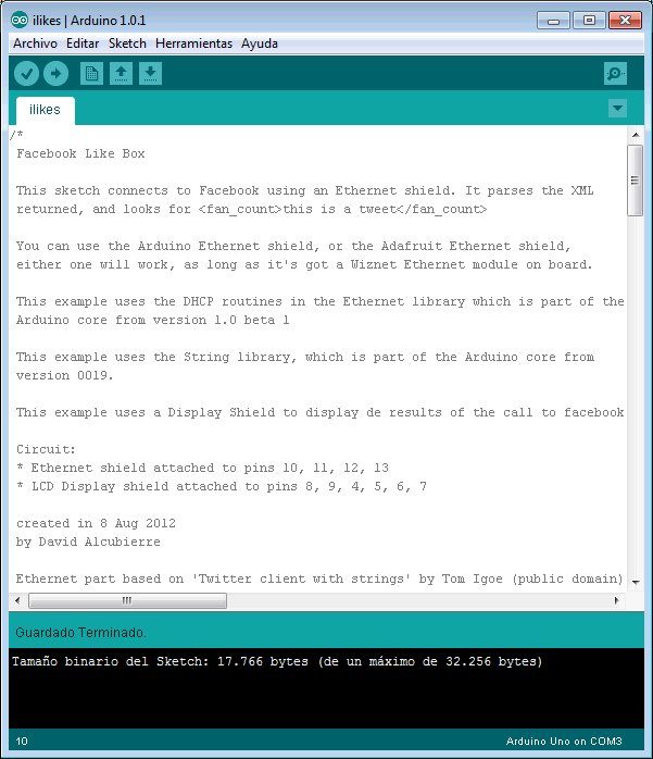
In this step you will customize the code that sends to the display the number of fans of our facebook page. First yo must install the Arduino software (in this exemple the 1.0.1 version is used, which can be downloaded for free from here) and open the file with the code of our program (once installed the Arduino software you must load it from the menu "File > Open"). The file can be downloaded from here (the file is named "ilikes.ino"). Once loaded you must see this:
You will need to make a couple of changes listed below:


This is the last step. You just need to load the program code into the mounted board. You must ensure that you have done the step 3 (cables must be connected) and click on the "Upload". Once this is done we're done :-)

The project has many possible improvements that have not been undertaken to make the process as simple as possible. One of them is the possibility of connect a Wifi Shield instead of Ethernet Shield (although more complicated settings). Another one is the possibility of connect the board to a battery (through a connector available on the main board). Another ones is the possibility of adding a diferent kind of display.
There are a lot of possibilities... :-)
 Spread the word:


